Overview
We have two types of OpenSK, V1 and V2. They have almost same schematic but different casing.
Currently, only V2 is available to the market.
OpenSK V2
![]()
It has a metal housing with only one button in the aft area.
NOTE
The LED and User button are together. The button material is transparent, so user can see LED light through the button.
Since the LED is behind the button, you have to check it from the aft area to find it breathing or flashing.
1. Switch To bootloader mode
After user connects the device to a computer, push and hold on the user button for more than 10 seconds and then release the button. If the red LED is breathing, OpenSK is in bootloader mode.
2. LED status
| LED behavior | Mode type | Trigger Method |
|---|---|---|
| Red LED is breathing | bootloader mode | Connect OpenSK to USB port, press the user button for more than more than 10 seconds and then release the button |
| Red LED is flashing | bootloader mode | Flash the firmware |
| No LED on | Working mode | Idle |
| R/G/B LED is flashing | Working mode | Wait for user presence when receiving FIDO command |
3. Hardware
The hardware schematic and PCB are shared here.
OpenSK V1
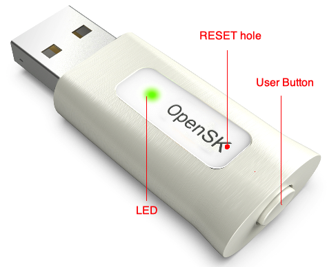
It has a 3D-printed case with one user button and one RESET button.
1. Switch To bootloader mode
After connecting OpenSK to the USB port, please insert a paper clip or a SIM-eject tool to the RESET button hole to switch it to bootloader mode. This is similar to user pushes the RESET button on the original nRF52840 USB dongle.
NOTE
The RESET button hole is covered by OpenSK label. So if you want to program the firmware occasionally, you can choose not to cover the label although we send the label to you together with OpenSK hardware.
2. LED status
| LED behavior | Mode type | Trigger Method |
|---|---|---|
| Blue LED is breathing | bootloader mode | Use a paper clip or a SIM-eject tool to push RESET button in RESET button hole |
| Blue LED is flashing | bootloader mode | Flashing the firmware |
| No LED on | Working mode | Idle |
| R/G/B LED is flashing | Working mode | Wait for user presence when receiving FIDO command |
3. Hardware
The hardware schematic and PCB files can be downloaded here.
Check Bootloader Mode
Sometimes, maybe you don't know whether your OpenSK is in bootloader mode after above operation, you can have three ways to check.
1. LED breathing
If the red LED is breathing, OpenSK is in bootloader mode, this is the simplest way.
2. macOS
2.1. lsusb command
On macOS, open Terminal.app, run
$ lsusb
If there is line similar to below message
Bus XXX Device YYY: ID 1915:521f Nordic Semiconductor ASA Open DFU Bootloader Serial: FFCCAE942A17
If there is line similar to below message
Bus XXX Device YYY: ID 1915:521f Nordic Semiconductor ASA OpenSK Serial: v1.0
2.2. USB Prober.app
On macOS, if you have USB Prober.app installed, run this app. If you have OpenSK attached and it is in bootloader mode, you should find USB information similar to below picture.
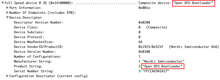
This means it is in bootloader mode.
2. Linux
On Linux (e.g., Ubuntu), Open Terminal.
After you plug in the USB dongle, or the USB dongle is changed between bootload mode and normal working mode, run lsusb on Terminal.
$ lsusb
Bus XXX Device YYY: ID 1915:521f Nordic Semiconductor ASA
Then run
$ dmesg
[ XXXX.YYYYYY] usb 2-2.8: new full-speed USB device number 24 using uhci_hcd
[ XXXX.YYYYYY] usb 2-2.8: New USB device found, idVendor=1915, idProduct=521f, bcdDevice= 1.00
[ XXXX.YYYYYY] usb 2-2.8: New USB device strings: Mfr=1, Product=2, SerialNumber=3
[ XXXX.YYYYYY] usb 2-2.8: Product: Open DFU Bootloader
[ XXXX.YYYYYY] usb 2-2.8: Manufacturer: Nordic Semiconductor
[ XXXX.YYYYYY] usb 2-2.8: SerialNumber: FFCCAE942A17
Otherwise, if your USB dongle is in normal working mode, the output message should be similar to
[ XXXX.YYYYYY] usb 2-2.8: new full-speed USB device number 22 using uhci_hcd
[ XXXX.YYYYYY] usb 2-2.8: New USB device found, idVendor=1915, idProduct=521f, bcdDevice= 0.01
[ XXXX.YYYYYY] usb 2-2.8: New USB device strings: Mfr=1, Product=2, SerialNumber=3
[ XXXX.YYYYYY] usb 2-2.8: Product: OpenSK
[ XXXX.YYYYYY] usb 2-2.8: Manufacturer: Nordic Semiconductor ASA
[ XXXX.YYYYYY] usb 2-2.8: SerialNumber: v1.0
[ XXXX.YYYYYY] hid-generic 0003:1915:521F.0009: hiddev0,hidraw2: USB HID v1.10 Device [Nordic Semiconductor ASA OpenSK] on usb-0000:00:1d.0-2.8/input0
NOTE
You'd better use sudo dmesg -c command instead of dmesg to output latest new added message.